Mighty IoT With MicroPython
Thanks for signing up for the workshop. We are DIY enthusiasts and big fans of Micropython.
The workshop materials are written using the MicroPython Documentation for ESP32.
Firmware Download
The ESP32 in the kit comes with the firmware installed on the hardware. For future firmware updates, the latest build of Micropython is available from here. (Todo: Tutorial on installing the firmware)
Workshop kit contents
Your workshop kit contains the following components:
- ESP32 Development Board
- AM2320 Digital Temperature and Humidity Sensor
- VEML6070 UV Index Sensor Breakout
- 1 x Neopixel in breadboard form factor
- 1 x Tactile Button
- 1 x Trim Potentiometer
- 1 x Red Led
- Jumper Wires
- Resistors (330 ohms x 1, 4.7K x 2, 10K x 1)
- Breadboard
Software setup
For the sake of convenience, we will be using the Thonny IDE to program in Micropython.
Mac Users: You can install Thonny by using pip (shown below). You will also need to install CP210x drivers for MAC.
pip3 install thonny
Linux Users: Install Thonny by using the following command:
bash <(curl -s https://thonny.org/installer-for-linux)
After installation, add your user id to the dialout and tty groups.
Note: You can program in MicroPython just using a text editor. You could even work off the Micropython Interpreter. Thonny makes your life easy by allowing you to load programs easily.
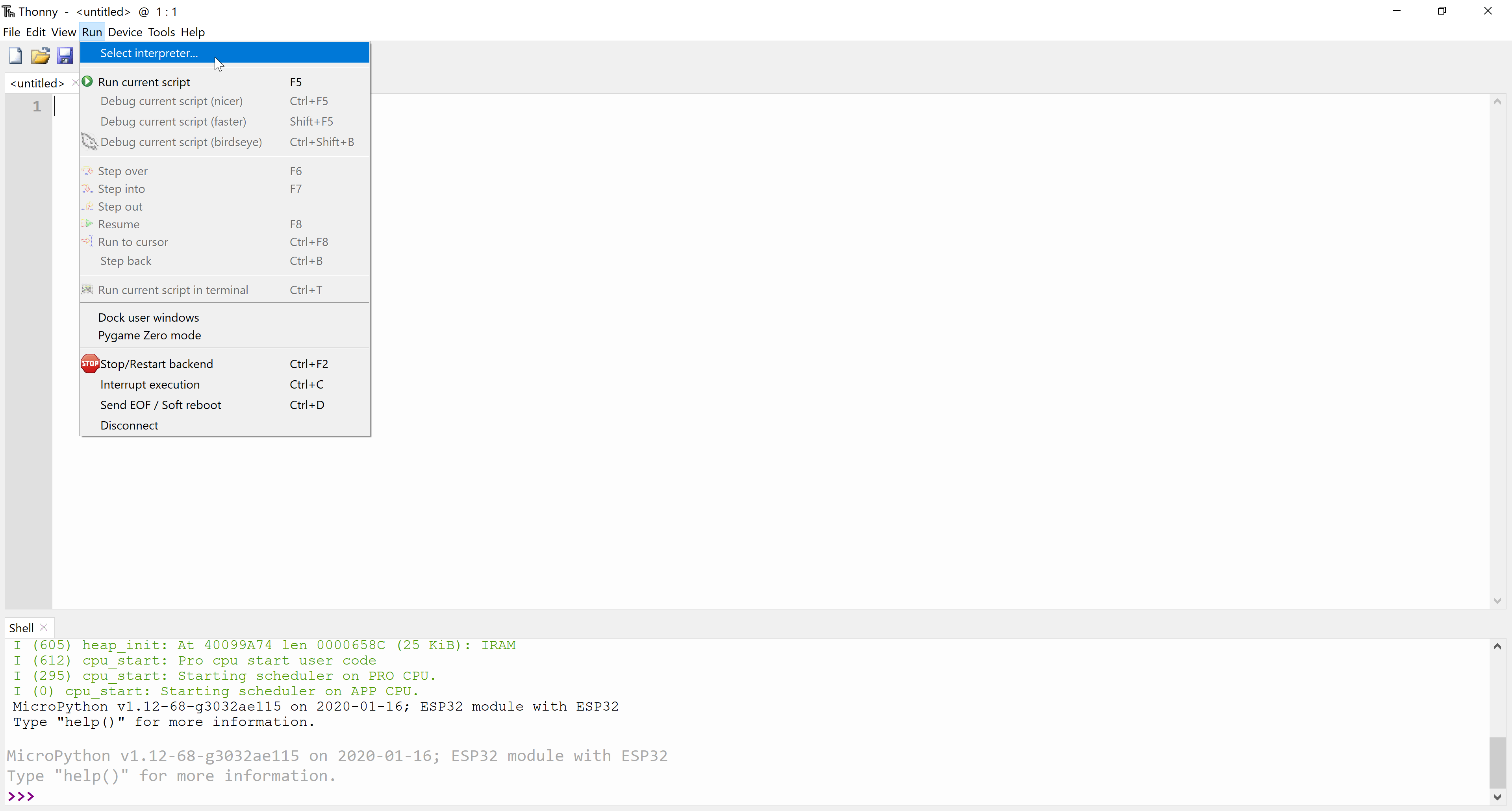
Once you have installed Thonny, launch the IDE and configure it for ESP32 on MicroPython as follows:
- Go to Run –> Select Interpreter:
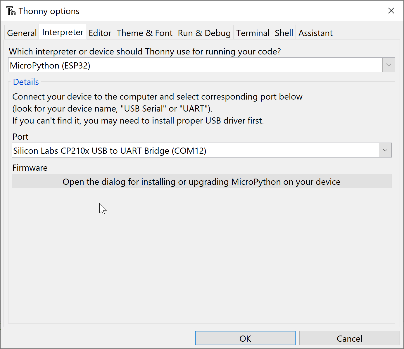
- Set the interpreter to Micropython (ESP32) and the port to your ESP32’s serial port (shown in the snapshot below). If you have a Windows machine and no serial ports were detected, you might have to install its drivers.
- Once the IDE is configured, the MicroPython interpreter on your ESP32 should be ready to use:
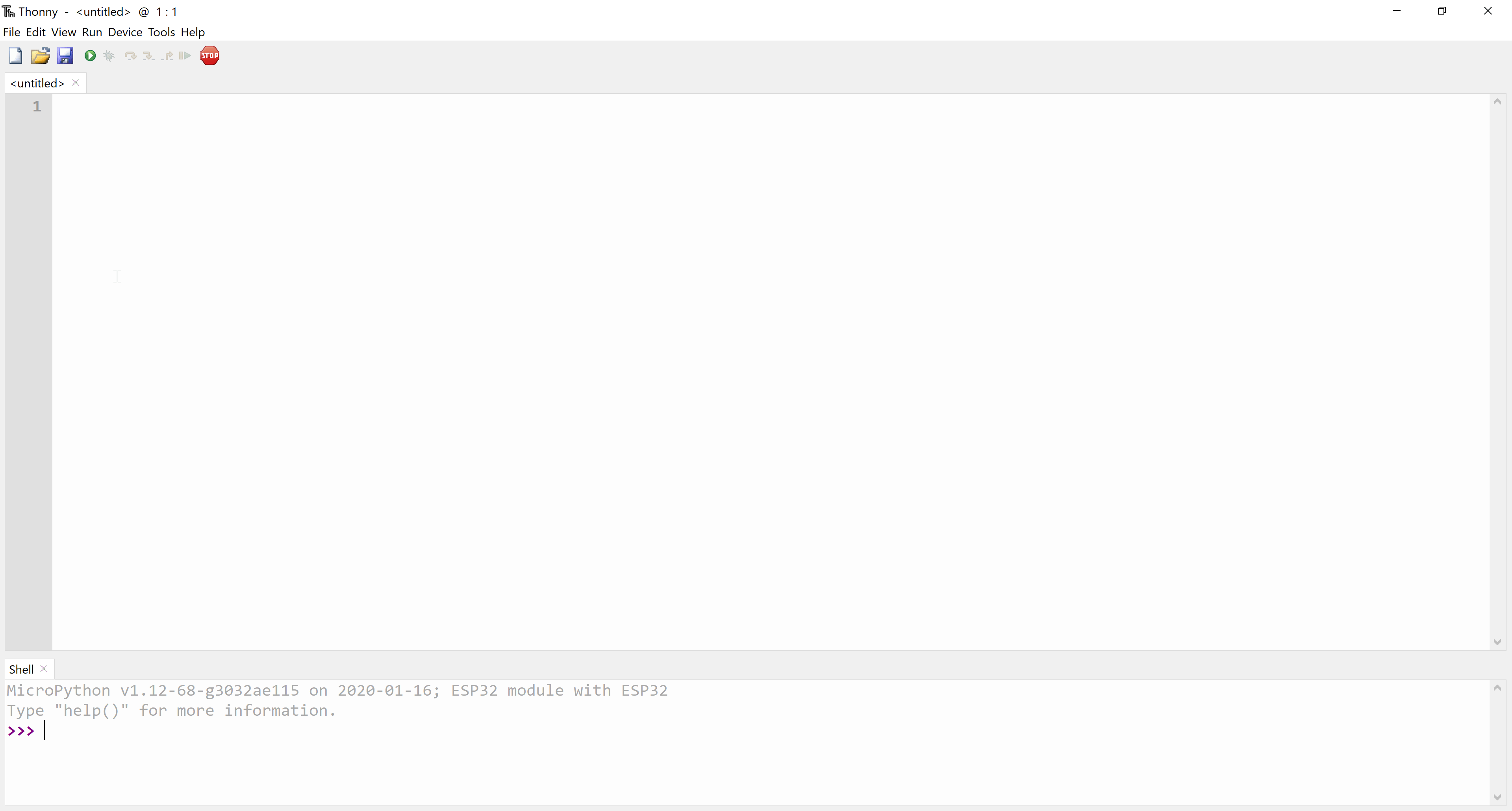
We are all set to get started with programming in Micropython
Hello World!
Let’s go ahead and print Hello World from the Micropython interpreter:
>>> print("Hello World!")
It should print Hello World! to the screen.

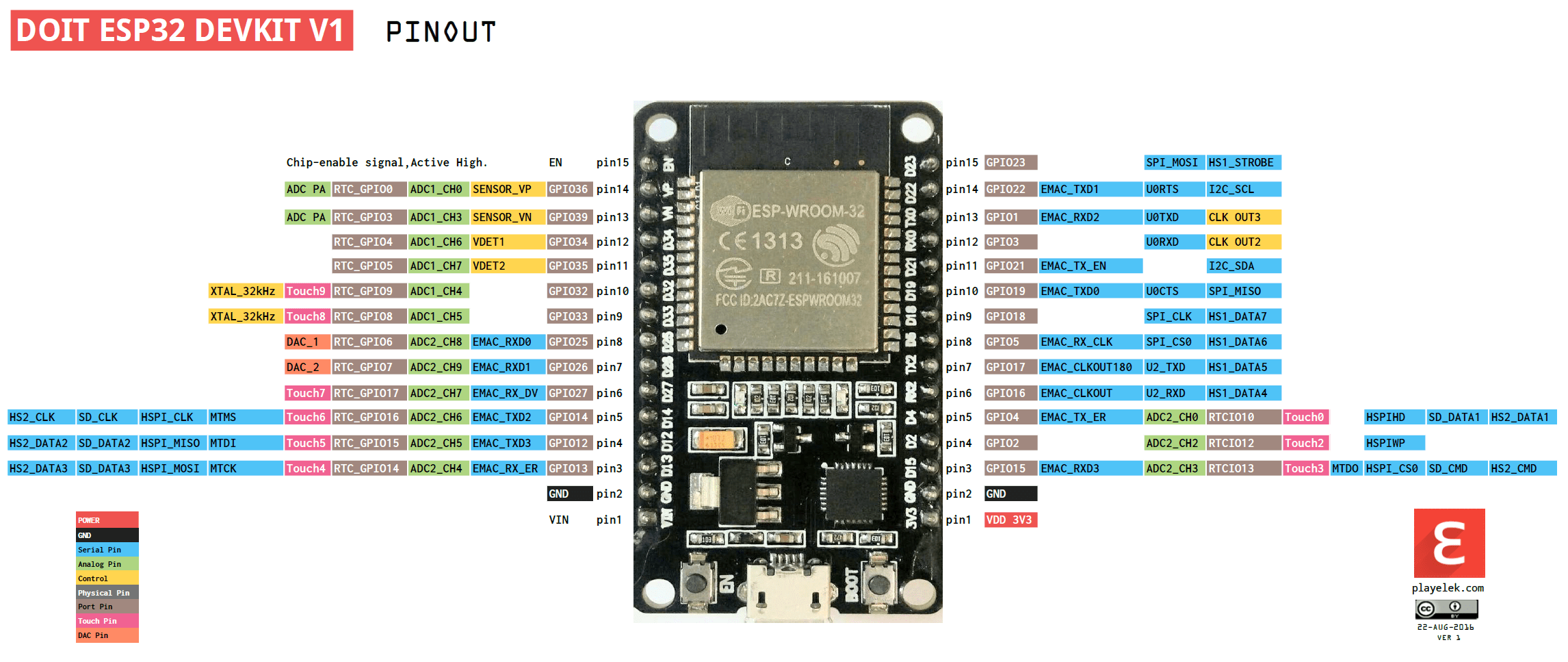
ESP32 Pinout
Before, we get started with hands-on programming, it is important to familiarize with the hardware. The board used for the workshop is the ESP32 Development Board. The schematic for the board is available from here. The image below describes the peripherals of the development kit. It describes the function of each pin:
We will be merely scratching the surface but we have included resources at the end for further learning.
Hello World - Embedded Style!
In the world of embedded devices, a hello world example is blinking an LED. According to the schematic, a blue LED is connected to the GPIO pin 2. We are going to blink an LED with one second interval. We are going to work on this example from the MicroPython interpreter. Let’s get started:
- The first step is to import the Pin class from the machine module. This enables controlling the pins on the ESP32.
>>> from machine import Pin - In order to blink with a one second interval, we need to introduce a delay between turning on and turning off the LED. We will be making use of the sleep function from the time module.
>>> from time import sleep - The next step is initialize the GPIO pin 2. We need to set it as an output pin:
>>> led = Pin(2, Pin.OUT) - We should be able to turn on the LED as follows:
>>> led.on() - Likewise, the LED could be turned off as follows:
>>> led.off() - The LED turns on/off when you call the on() and off() methods. Let’s make it blink using a while loop:
  while True:
   led.on()
   sleep(1)
   led.off()
   sleep(1)
Make a note of the indentation in the while loop. The LED onboard should be blinking with a one second interval.
Running a script
In our example, we were working from the MicroPython interpreter. The program will stop running if you hit the reset button or power off the ESP32. Let’s write the code sample discussed above as a script. Putting it all together:
from time import sleep
from machine import Pin

led = Pin(2, Pin.OUT)
while True:
   led.on()
   sleep(1)
   led.off()
   sleep(1)
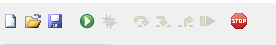
- From the toolbar, click on Run Current Script (F5), the green play button shown in the snapshot below:
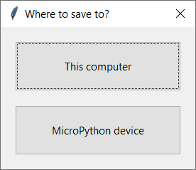
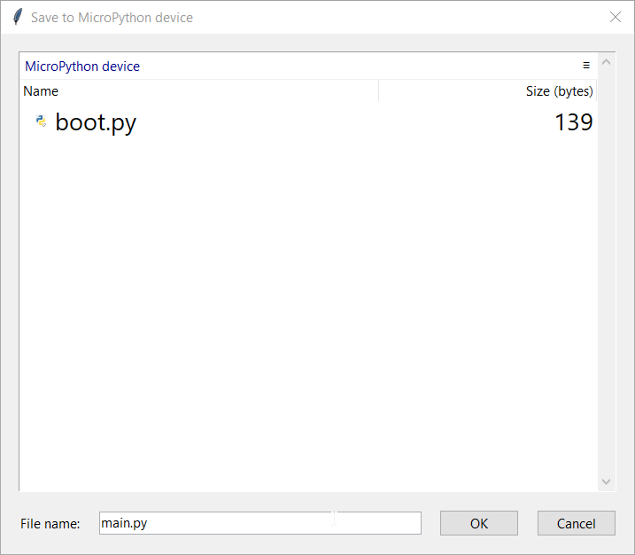
- Save to MicroPython device.
- Save the file as main.py. Any file saved as main.py loads automatically upon reset. Try resetting your device and see if it loads automatically.
Breadboard Blinky
You are welcome to skip this example but you get to breadboard a blinky circuit using the ESP32. For this exercise, we will need the following items (provided in the kit):
- ESP32 Development Board
- 1 x LED
- 220 ohm resistor
Connect the LED to GPIO pin 23 using a 220 ohm resistor (to limit current) as shown in the figure below:
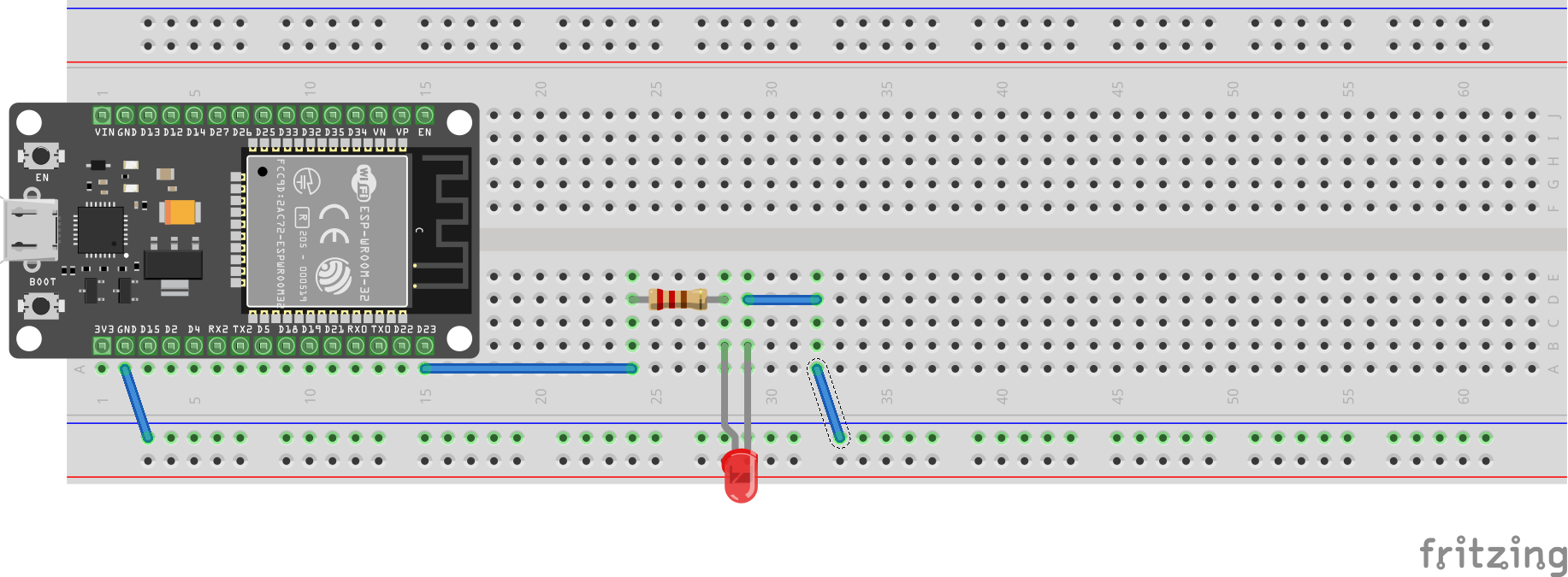
In case you are not familiar with prototyping with a breadboard, one end of the 220 ohm resistor is connected to GPIO pin 23. The other end is connected to the anode of the LED. The cathode is connected to ground.
Now that we have completed the basic example, let’s move on to the next section!
Interfacing a Button
In this section, we are going to detect button presses. Connect a button to the ESP32 as shown in the figure below:
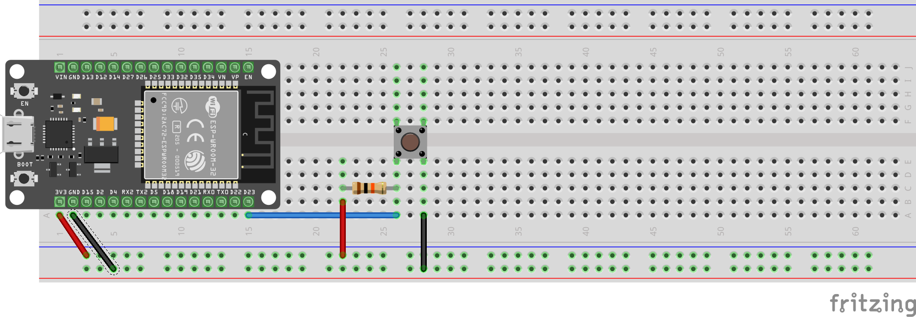
In the schematic, the GPIO pin 23 is pulled upto 3.3V using a 10K resistor. One end of the momentary press button is connected to the junction of the 10K resistor and pin 23. The other end is connected to ground. Let’s write some code!
- The first step is to import the Pin Class:
from machine import Pin from time import sleep - Initialize pin 23 as an input:
d23 = Pin(23, Pin.IN) - Let’s read the pin states using a while loop:
  while True:
 print(d23.value())
 sleep(0.1)
Go ahead and try the pressing the button. Is the button state switching between high and low?
Analog to Digital Converter (ADC)
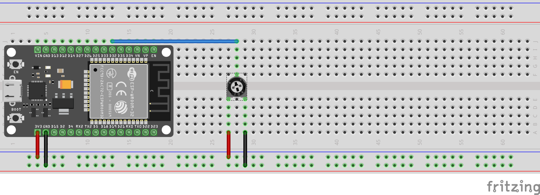
In this section, we will learn to use the Analog-to-Digital Converter on the ESP32. Currently, the ADC drivers are only for pins 32-39 (Refer to the pinout diagram above). This is due to a conflict with Wi-Fi interface driver. Connect a potentiometer to pin 32 as shown in the figure below:
Note: The snippet for the ADC is from the Micropython Quick Reference for ESP32 documentation.
from machine import Pin, ADC
from time import sleep
adc = ADC(Pin(32))          # create ADC object on ADC pin
adc.atten(ADC.ATTN_11DB)    # set 11dB input attenuation (voltage range roughly 0.0v - 3.6v)
adc.width(ADC.WIDTH_12BIT)   # set 12 bit return values (returned range 0-4096)

while True:
    print(adc.read() * (3.3/4096))
    sleep(1)
Turn the potentiometer knob and see if the voltage varies.
Neopixel
Neopixels are RGB LEDs that can be controlled individually. In case you are not familiar with Neopixels, here is a guide from Adafruit. Neopixels usually are connected in series. In this exercise, we are going to be running some light effects on a single neopixel. Your kit contains a single neopixel.
The neopixel drivers are available with the MicroPython binary. Connect your neopixel as shown in the figure below:
![]()
The neopixel can run with 3.3V. A neopixel can be connected in series. Hence they have both in and out pins. In the schematic, the GPIO pin 23 is connected to the In pin. A second neopixel could be connected to the Out pin of the first one. Let’s test the neopixel by setting it to red color.
from machine import Pin
from neopixel import NeoPixel

pin = Pin(23, Pin.OUT) # set gpio pin 23 to output
np = NeoPixel(pin, 1)  # set the number of pixels to 1
np[0] = (255, 0, 0)    # set color to red
np.write()             # write it to neopixel
It is also possible to create some light effects using neopixels. For example: An RGB fade in/out light effect can be created as follows:
while True:
    for i in range(0, 4 * 256, 8):
        if (i // 256) % 2 == 0:
            val = i & 0xff
        else:
            val = 255 - (i & 0xff)
        np[0] = (val, 0, 0)
        np.write()
        time.sleep(0.1)
Exercise: Try writing a light effect where the neopixel fades into different colors in cycles.
Publishing UV index data to the cloud
Your kit comes with a VEML6070 sensor. We will calculate the UV index and publish it to the cloud. We will be making use of the ThingSpeak platform.
Note:: The ThingSpeak code samples were built based upon this tutorial.
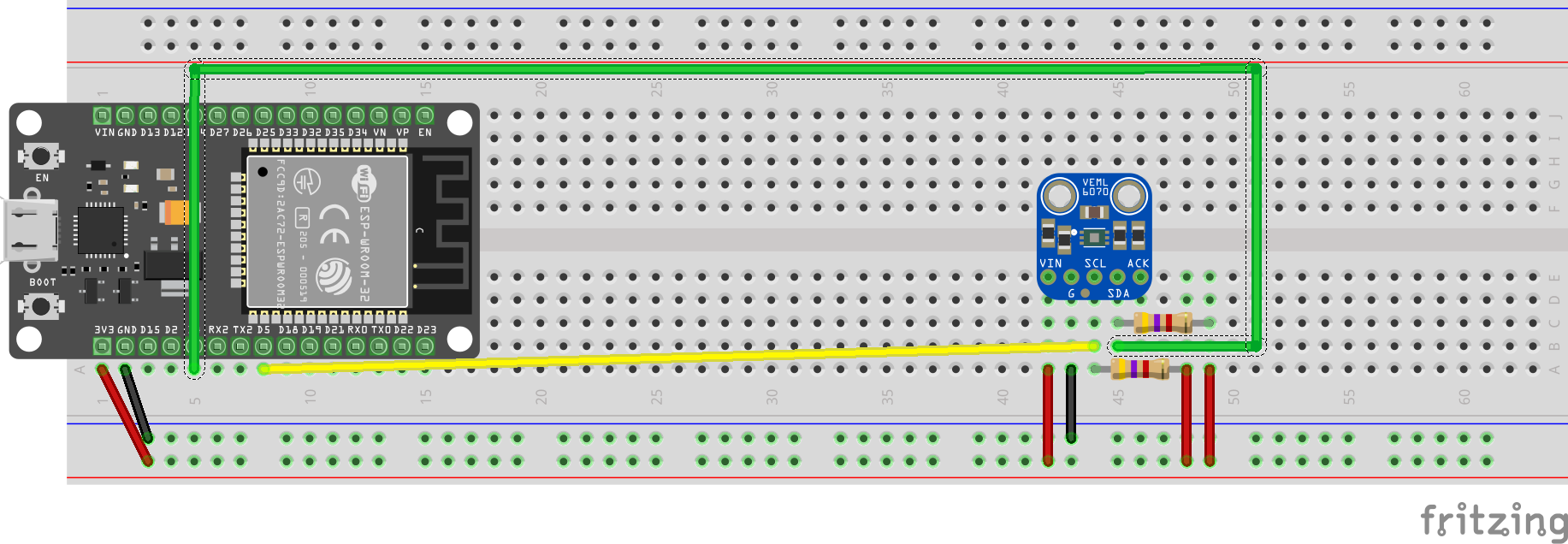
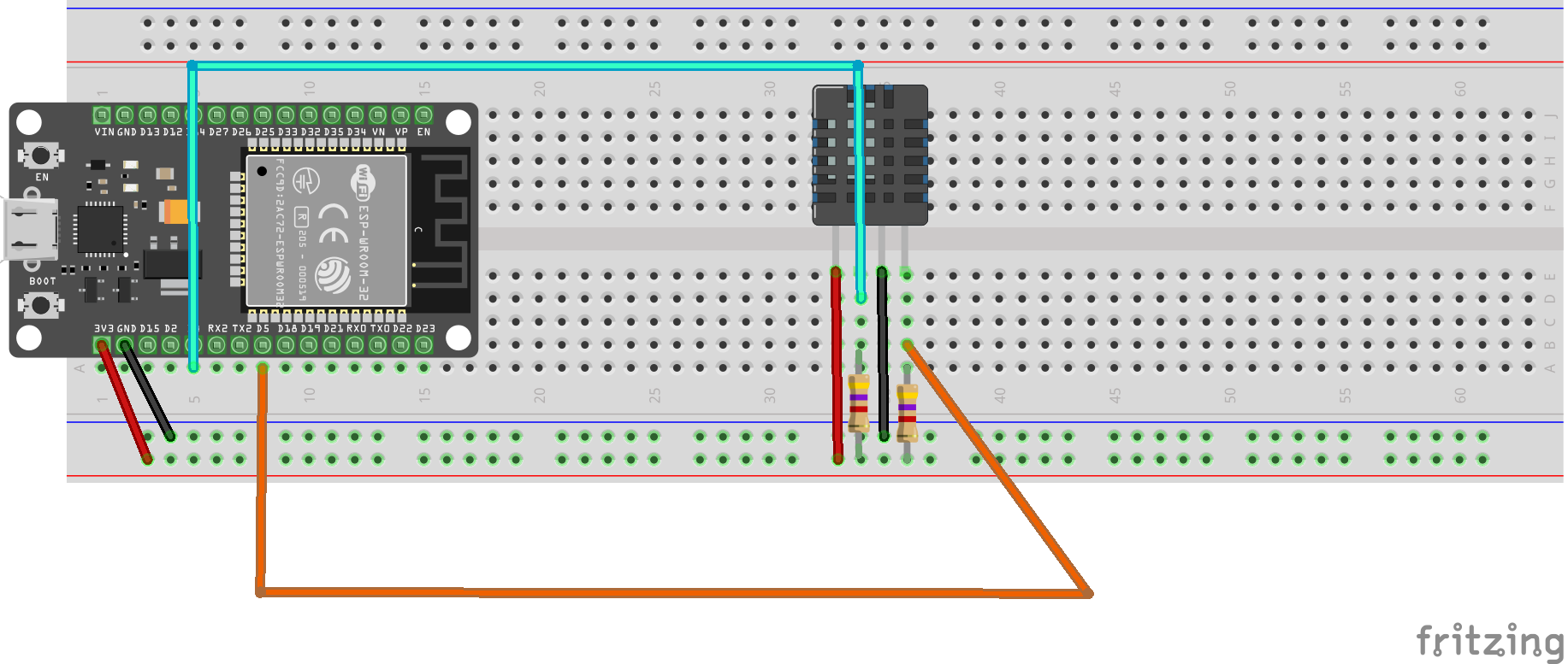
- The VEML 6070 breakout comes with an I2C interface. Connect it to the ESP32 as shown in the figure below. The sensor is powered using 3.3V. The SCL and SDA pins of the VEML6070 are connected to pins 5 and 4 respectively. Due to the open drain configuration of theI2C interface, the pins are pulled up using 4.7K resistors.
- The VEML6070 sensor’s drivers are already loaded onto your ESP32. Let’s test to make sure that everything works.
-
The first step is to initialize the I2C interface and initialize the VEML6070 drivers.
from time import sleep from machine import I2C, Pin import veml6070 i2c = I2C(scl=Pin(5), sda=Pin(4)) uv = veml6070.VEML6070(i2c) -
After initialization, we can print out the UV index values at regular intervals:
while True: uv_raw = uv.uv_raw risk_level = uv.get_index(uv_raw) print('Reading: ', uv_raw, ' | Risk Level: ', risk_level) sleep(1) -
The MicroPython terminals starts printing the UV index values. It is time to test it with a UV torchlight. Did the index values vary? Note: UV Torchlights can be harmful to the eyes. Care should be taken while handling it and do not make direct contact.
- Your ESP32 board is already connected to the internet. You can follow the network connection instructions from here. You can verify using the code snippet below. It should print out the IP address:
>>> import network >>> wlan = network.WLAN(network.STA_IF) >>> wlan.ifconfig() ('192.168.86.34', '255.255.255.0', '192.168.86.1', '192.168.86.1') -
Let’s publish the UV index values to Thingspeak. Sign up for a free account.
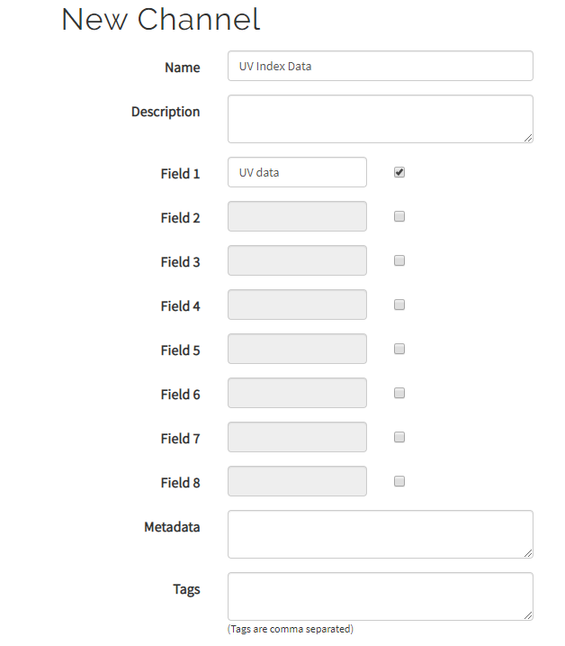
- Create a new channel to record your incoming data.
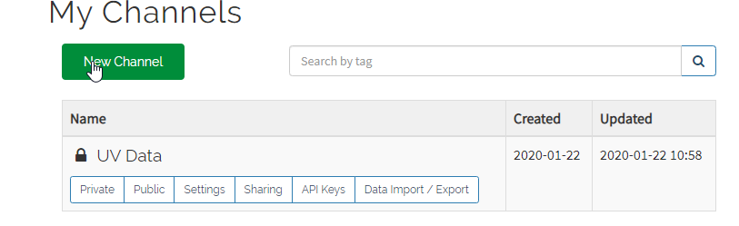
- Assign a name to your channel and rename Field 1 to UV data.
- Make a note of your channel id from the landing page of your channel
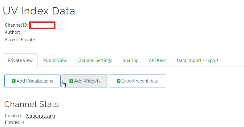
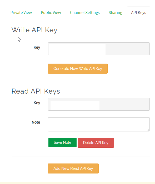
- Make a note of your write API key.
-
Let’s edit our UV sensor code sample to publish data to ThingSpeak. Make sure to use your ThingSpeak channel id and API key.
import network
from time import sleep
from machine import Pin, I2C
from umqtt.simple import MQTTClient
import veml6070

i2c = I2C(scl=Pin(5), sda=Pin(4))
uv = veml6070.VEML6070(i2c)

SERVER = "mqtt.thingspeak.com"
client = MQTTClient("umqtt_client", SERVER)

CHANNEL_ID = "ID"
API_KEY = "KEY"

topic = "channels/" + CHANNEL_ID + "/publish/" + API_KEY

def do_connect():
    wlan = network.WLAN(network.STA_IF)
    wlan.active(True)
    if not wlan.isconnected():
        print('connecting to network...')
        wlan.connect('ssid', 'password')
        while not wlan.isconnected():
            pass
    print('network config:', wlan.ifconfig())

do_connect()
while True:
    uv_raw = uv.uv_raw
    risk_level = uv.get_index(uv_raw)
    print('Reading: ', uv_raw, ' | Risk Level: ', risk_level)

    payload = "field1=" + str(uv_raw)
    client.connect()
    client.publish(topic, payload)
    client.disconnect()
    sleep(10)
-
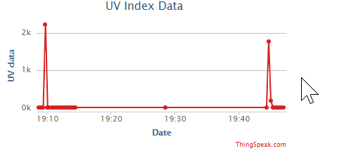
If everything was set correctly, you should be able to view your data on ThingSpeak (shown in the snapshot below).
Temperature/Humidity sensor
In this section, we will interface an AM2320 sensor to the ESP32 and we will be using the modified AM2320 drivers. The AM2320 sensor needs to be interfaced to the ESP32 as shown in the figure below:
The AM2320 drivers are loaded onto your ESP32. Let’s take it for a spin:
>>> import am2320
>>> import time
>>> from machine import I2C, Pin
>>> i2c = I2C(scl=Pin(5), sda=Pin(4), freq=100000)
>>> sensor = am2320.AM2320(i2c)
>>> while True:
      sensor.measure()
      print(sensor.temperature())
      print(sensor.humidity())
      time.sleep(4)
If there are problems reading the temperature from the sensor, check your connections and ensure that there is a pull-up resistor on the clock and data pins.
Exercise: Create a new channel and upload the temperature and humidity as separate fields to ThingSpeak.
Online PyBoard
WebREPL
Further Learning Resources
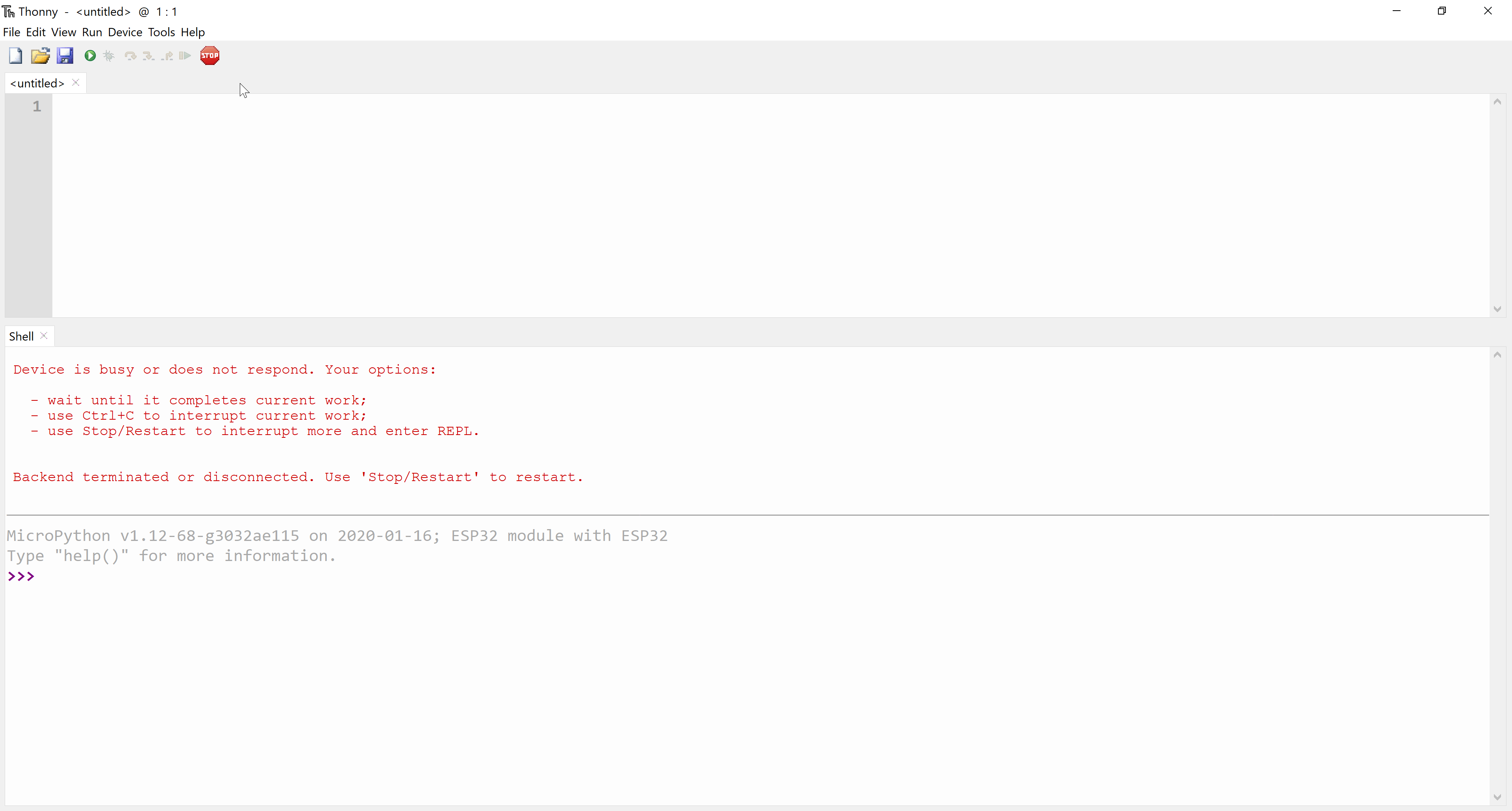
Troubleshooting
- If your MicroPython interpreter is not responding (as shown in the snapshot below), reset your ESP32: